This deep dive discusses BxBChan customization. First, it discusses
each parameter used for customization. Second, it discusses how to
select a BxBChan filter. Filter coefficients are critical, and
require extensive DSP knowledge to create. Thus there is help.
Each BxBChan delivery includes a wide variety of precalculated
filter coefficients, with performance curves specific to that
BxBChan that simplify the selection.
BxBChan Customization Parameters
The BxBChan has several types of customization parameters that fit it
to almost any high-speed application. The first type of parameters is
those that must be set at delivery time.
Delivery-Time Parameters
These parameters must be chosen on delivery because they are highly
related to performance optimizations, and thus selecting them at
delivery time means that those optimizations can be applied to
provide the highest BxBChan performance. Changing these options
requires a new delivery. These are the delivery-time parameters:
1. Number of Channels (NUM_CHANNELS)
The number of channels is the primary parameter of a polyphase
filter bank channelizer. Channels are slices of bandwidth that
are extracted from evenly spaced sections of the original
bandwidth. They are resampled to a lower sampling rate than the
original bandwidth, which makes them easier to process. The
number of channels must be an FFT size, which for most
channelizers would means it must be a power of 2. However, the
BxBChan supports additional sizes -- any size that is a multiple
of powers of 2, 3, 5, and 7. For example, a 7000-channel
BxBChan is supported.
2. Real-to-Complex or Complex-to-Complex
BxBChans can process real input samples or complex input
samples, and this parameter selects which type of channelizer it
is. Real samples are convenient if the data is coming directly
from an ADC. In this case, selecting a real-to-complex BxBChan
avoids the distortion of a separate real-to-complex filter that
is included in some designs. Complex samples may be the input
if the channelization is later in the processing, or if the ADC
performs complex sampling with inphase and quadrature
components. Samples of output channels are always complex.
3. Oversampling Ratio
In order to reduce aliasing, channelizers often produce output
channels with oversampled outputs. The most common oversampling
ratios are 1:1 (Critically sampled) and 2:1. 1:1 is used when
aliasing is not important. 2:1 is used when aliasing is
important, and filter complexity is to be minimized. Other
oversampling ratios such as 4:3 or 8:7 give lower output data
rates. This can give lower downstream workload, especially if
the data is to be stored or routed over a network. Although
output data rates are lower as the oversampling ratio gets
closer to 1:1, the filters required to reduce aliasing get
increasingly large. When the BxBChan has a non-power-of-2
number of channels, it supports a wider range of oversampling
ratios than can be efficiently supported by a power-of-2
channelizer.
4. Points per Clock in (PPC_IN)
BxBChans can process multiple input points simultaneously, so
that they can process ADC sampling rates that are higher than
the FPGA clock rate. PPC_IN is a measurement of how many
complex input points are processed each clock. (If it is a
real-to-complex BxBChan, the number of real points processed is
twice this.) Note that in the literature PPC_IN is also
sometimes called the SuperSample Rate (SSR) or the number of
phases.
5. Points per Clock out (PPC_OUT)
BxBChans can process multiple output points simultaneously.
PPC_OUT is a measurement of how many complex output points are
processed each clock. Note that if, for example, the
oversampling ratio is 2:1, then the output data rate is twice as
high as the input data rate. In this case, PPC_OUT must be at
least twice PPC_IN, or else the ratio of BxBChan output clock
frequency to input clock frequency must be 2 or greater. This
is necessary so that the number of output points per output
clock can keep up with the data rate. When the BxBChan has a
non-power-of-2 number of channels, it supports PPC_OUT values
that can't be supported by a power-of-2 channelizer. For
example, a 7000-channel BxBChan could support PPC_OUT values of
2, 5, 7, 10, 14, 35, 70, etc. This can be convenient for
matching ADC sampling rates with FPGA clock rates. When only
powers of 2 are allowed for PPC_OUT, it can be a big jump
between PPC32 and PPC64. For example, an ADC at 60Gsps with an
oversampling ratio of 2:1 generates 60Gsps complex out of a
channelizer. If it's a power-of-2 channelizer, this means the
FPGA clock rate can be 60Gsps/PPC64=937MHz or
60Gsps/PPC128=468MHz. But if other values are possible, say
PPC100, then other options are available for FPGA clock rate,
such as 60Gsps/PPC100=600MHz. Sometimes this can be useful for
matching the necessary ADC sampling rate with the desired FPGA
clock rate.
The next type of parameters are those that affect algorithmic
performance.
Algorithmic Parameters
These parameters affect the algorithmic performance of the
channelizer -- i.e. noise and aliasing. They can be changed by
customers at compile time, after delivery. Changing them will
sometimes also change resources, speed, and power. Changing them is
something of an art. To help guide you in their selection,
numerous performance curves are included with each release,
highlighting the results of different values. These are the
algorithmic parameters:
6. Filter NUM_TAPS
Total filter length of a channelizer is equal to
NUM_TAPS*NUM_CHANNELS. Higher values of NUM_TAPS give longer
filters that allow less aliasing.
7. Filter Coefficients
After selection of the NUM_TAPS, filter coefficients of the
correct filter length must be selected. There are an infinite
number of filter choices, but some of the best ones are included
in the delivery for a range of different values for NUM_TAPS. A
full discussion of the included filters and their provided
performance curves is given below. It is also possible for
customers to explicitly specify their own filter coefficients.
8. Filter FILTER_BITS
Filters coefficients start as real numbers; they are not fixed
point. However, for the channelizer implementation they must be
fixed point. The release includes tools to change the
real-valued filter coefficients into fixed-point values of the
desired bit width for use in the BxBChan. Top-level BxBChan
parameters then select the appropriate filter file and bit
width. Performance curves are supplied showing how different
filter bit selections affect filter shape. Note that unlike FFT
coefficients, quantizing filter coefficients doesn't introduce
quantization noise. Instead, if affects filter shape which
affects passband ripple and aliasing.
9. FFT Data Bits
The number of FFT Data Bits affects the rounding error that
occurs inside each FFT stage of the BxBChan. It also affects
speed and resources.
10. FFT Amplitude Management
There are multiple controls for management of FFT amplitude.
Mostly these are compile-time, although there are also controls
for run-time monitoring and control. Amplitude must be
controlled because if amplitudes are low, there is excess
rounding error in the FFT. If amplitudes are high, there is too
high a probability of overflow. The primary difference between
floating-point FFTs and fixed-point FFTs is that for fixed-point
FFTs, this amplitude control must be performed to get good
results. The primary benefit of floating point is that this
amplitude control is automatic. In most practical applications,
high FFT Data Bits can be selected and limited amplitude control
can be performed to give better performance per watt in a
fixed-point FFT than any floating point implementation can
achieve. One other problem with amplitude management is that
its control is often somewhat arcane. The BxBChan provides
optional easier-to-use controls that simply the problem
immensely.
The next type of parameters are those that affect data formats.
Data Format Parameters
These parameters affect the order of data in/out of the BxBChan.
These are the data format parameters:
11. Input Bit Width
The number of Input Bits affects memory utilization in the
BxBChan's filter stage. In some situations, the actual ADC data
may be 12-bit or 14-bit, but it comes packed into 16-bit words.
In these cases, it should be unpacked into its actual size to
save significant front-end memory. Input data is always in
natural order.
12. Output Bit Width
The number of Output Bits is often set to something less than
the number of FFT Data Bits, since additional FFT Data Bits are
often kept to reduce rouding error. Output bits are rounded to
this value. This is for convenience; it has little effect on
resource usage.
13. Output Data Order
Output data order can be set to Fully Natural Order or Partially
Natural Order. Usually Fully Natural Order is selected, in
which the first PPC_OUT samples are all on the same clock.
Partially Natural Order has the first sample on each clock
matching the clock number of the output. The second sample
matches the clock number plus the total number of clocks. This
Partially Natural Order is sometimes beneficial for the BxBFFT,
and thus has been preserved, but has no known application yet
for the BxBChan. It doesn't save significant resources.
14. Output Zero Location and Nyquist Zone
There are controls to select whether data comes out in a forward
or reverse order. The reverse order is useful if an ADC is
operating in the 2nd or 4th Nyquist Zone, in which case the data
is flipped. Reverse order flips it back. For complex BxBChans
only, the data order can put zero frequency in the center.
The next type of parameters are those that pipelining of the implementation.
Pipelining Parameters
Pipelining parameters have no effect on the output data values,
except for the delay in producing them. Instead, these parameters
add pipelining registers to help the BxBChan meet timing. Changing
these parameters is primarily useful in designs with high resource
contention. These are the pipelining parameters:
15. Pipelining Default
This is a global control that selects default values for all
pipelining controls that aren't individually overridden.
16. Individual Pipelining Controls
There are many individual pipelining controls, the number of
which varies with the channelizer type and the number of
channels. There are pipeline controls both for the BxBChan
filter and for individual stages of the BxBChan FFT.
Memory Parameters
Memory parameters have no effect on the output data values, except
for the delay in producing them. Instead, these parameters select
which types of memory to use in various places within the BxBChan.
Selections can be made between distributed memory and block memory.
In some cases, selections can be made between the different types of
block memory. In addition, for FFT twiddle stages the twiddle
generation can be pushed into an on-the-fly calculation circuit,
which eliminates almost all of the memory usage from that twiddle
stage. These are the memory parameters:
17. Block Memory Desirability in Percent
Normally small memories are fit into distributed RAM and large
memories are fit into block RAM. This desirability percentage
changes the calculation to encourage or discourage placement of
memories in block RAM. There are multiple controls for this,
including a global default and settings for the BxBChan filter,
the FFT front-end I/O, and each FFT stage.
18. Twiddle Source
For each FFT stage, the FFT twiddles can be selected to be
automatically generated instead of stored in a table. The
on-the-fly generator uses extra fabric resources and DSPs, but
can save significant memory resources.
19. FFT I/O Memory Forcing
There are controls to force a specific percentage of FFT I/O
memory into block RAM. These are seldom used; their purpose is
for designs that are exceeding 100% memory utilization to be
able to shift I/O memory utilization between memory types by
controlled amounts to make the design close.
Selection of Filter Coefficients
Selection of filter coefficients involves selecting the number of
filter taps, selecting the real-valued coefficient values, and
selecting the fixed-point width to quantize those values to.
The BxBChan ships with multiple filter options that are designed for
the most common channelizer applications. These filters are Slepian
filters, a type that is optimal for highest passband energy and
lowest sidelobe power. Or if you wish, you can have BxB generate
custom coefficients specifically for you. You can also specify your
own filter coefficients when you configure the BxBChan.
When choosing from among the supplied filter coefficients, the first
selection is usually the type of filter coefficients, based on the
goal of the channelization. This decision can be simplified to the
number of dB down at the crossover point of the channel. In one
case, the number of dB down at the folding point of the channel is
also important.
The crossover point of the channel is the half-way point between two
different channels in the original bandwidth. This is where one
channel "stops" and the other takes over. Of course, filters aren't
perfect so in actuality the filters for these channels don't stop,
they overlap. At what dB level they overlap at the crossover point
is critical.
The folding point of a filter is the furthest extent of the
bandwidth supported by the BxBChan's output channel sampling rate.
Thus it varies with the oversampling ratio. For a 1:1 oversampled
BxBChan, the crossover point and folding point are the same. For a
2:1 oversampled BxBChan, the folding point is twice as far from the
channel center as the crossover point. Any spectral energy in the
input bandwidth that is beyond the folding point of the filter
aliases and becomes distortion in the output channel. This point is
sometimes important for filter selection, but always important for
selecting the number of taps.
The most common filters fall into these cases:
0dB down at crossover
This filter type is used when, for example, when you want to
measure sine wave amplitudes accurately without any dip between
channels. A sine wave near the crossover point will be in both
channels. In one of the channels it will have accurate amplitude.
3dB down at crossover, full down at folding
Filters that are 3dB down at crossover are generally used to
capture variable bandwidths using multiple channels. These
bandwidths can then be reconstructed with inverse channelizers,
sometimes called synthesizers, such as the BxBDechan. If the
BxBDechan uses the same filter as the BxBChan, the
double-filtering will produce an amplitude that's 6dB down at
the crossover point. 6dB down is half amplitude. This causes
each of two neighboring channels to provide half amplitude at
the crossover point, and thus they fill in for each other and
this portion of the original bandwidth is reconstructed with
what can be very low distortion or ripple. Having the filter be
full down at folding means that the dB down at the folding point
matches the dB down of stopband rejection of the filter. This
is useful to prevent aliasing into the channel.
3dB down at crossover, half down at folding
This type of filter is like the 3dB down filter that's full-down
at folding, except the number of dB it's down at folding is half
that of the full-down filter. This allows aliasing into the
band. However, when following the BxBChan immediately by a
BxBDechan, that aliasing is at frequency points that are also
reduced by the BxBDechan, and thus it is effectively removed.
This may work or may not work if there is processing between the
BxBChan and BxBDechan. When it works, it allows higher filter
performance at the same number of filter taps.
6dB down at crossover
This filter is more of a standard lowpass filter design. If you
want to have very little aliasing with low numbers of filter
taps, this is a good choice.
Choosing which filter to use is aided by this filter selection
graph. One of these is included in each BxBChan release package,
with the response measured specifically for that BxBChan:
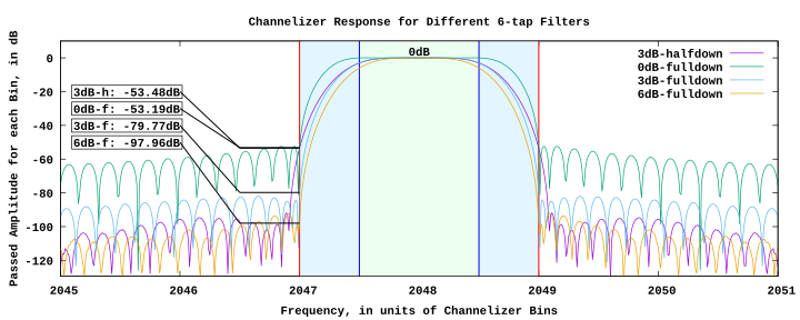 Note that this graph clearly shows the crossover point, which is the
dividing line between the green and blue areas. It also clearly
shows the folding point, which is the dividing line between the blue
and white areas. For this channel, the green area is the passband.
The blue area is the transition band. The white area is the
stopband.
Note that this graph clearly shows the crossover point, which is the
dividing line between the green and blue areas. It also clearly
shows the folding point, which is the dividing line between the blue
and white areas. For this channel, the green area is the passband.
The blue area is the transition band. The white area is the
stopband.
This graph gives the general shape of each filter type for 6-tap
filters. Of course, as the number of taps increases the stopband
performance improves. When you order a BxBChan, you can specify how
many taps you are likely to use, and that value will be used for
this graph.
Once you select a general filter type, you may want to fine tune the
number of taps. There are graphs for that for each filter type.
Here is the one for this example for a 3dB-down, full down filter:
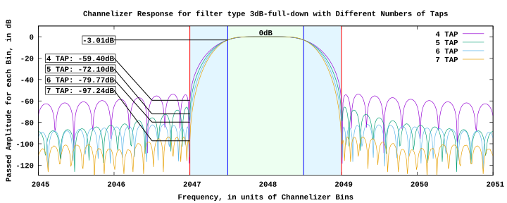 This helps narrow down the number of taps. Selecting higher numbers
of taps gives better performance, but uses more resources.
This helps narrow down the number of taps. Selecting higher numbers
of taps gives better performance, but uses more resources.
Once you have narrowed down the number of taps, you will want to
select the number of filter bits that the filter is quantized to.
Lower numbers of filter bits give a more efficient implementation.
Below a certain level, they introduce filter shape distortion.
Here is the graph you would use to select the number of filter bits:
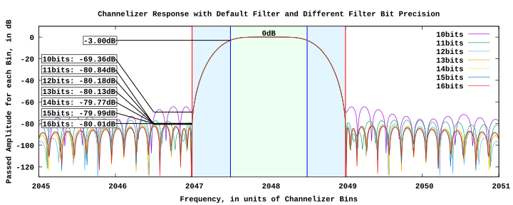 This particular plot is not tailored to the specific filter type and
number of taps that you have selected. However, it does give an
idea of the number of filter bits that start to cause filter
distortion.
This particular plot is not tailored to the specific filter type and
number of taps that you have selected. However, it does give an
idea of the number of filter bits that start to cause filter
distortion.
Once a filter is selected, the user guide tells how to use the
supplied tool to truncate the supplied real-valued input filters to
the desired number of bits. It then tells how to configure the
BxBChan to use the new coefficients.
Conclusions
Configuring the BxBChan to customer needs is made as simple as
possible, yet the configuration process has significant power to
provide a very wide range of desirable customizations.
The configuration process gives expert-level control without the
expert-level cost.
Links
Phone Contact: +1-623-487-8011 (this has automated call screening)
 BxBChan Customization Deep Dive